

Introduction
There were a few projects in the last year that just didn't work. Mostly because they were too ambitious and I did not have enough time and pacience to finish them. So I finally wanted to build a robot that just works without any gimmicks.
Electronics
The main part of the robot is an Atttiny85 again.
The servos are two HXT900 from Hobbyking:
http://www.hobbyking.com/hobbyking/store/__662__HXT900_9g_1_6kg_12sec_Micro_Servo.html
I removed the potentiometers and the end stops, so that they are continuously rotating.
http://www.hobbyking.com/hobbyking/store/__662__HXT900_9g_1_6kg_12sec_Micro_Servo.html
I removed the potentiometers and the end stops, so that they are continuously rotating.
I am using a 3,7V 600mAh LiPo to power both the Attiny and the servos. A small power switch disconnects the battery after use.
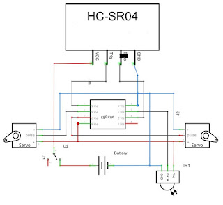
An HC-SR04 ultrasonic sensor enables autonomous driving to a certain degree.
To control the robot a 38kHz infrared receiver is needed as well.


Hardware
For the body of the robot I wanted to make use of my 3D printer. There are two half shells that hold the servos, the ultrasonic sensor and all remaining electronic components. These halves are connected by four screws. The holes are designed to fit the mounting screws that came with the servos. Both wheels are screwed into the servo shafts. The heavier parts like the battery need to be in the lower half to help the robot remain balanced.


The stl-files are available on Thingiverse:
Depending on your printer and servos you will have to sand the shells down a bit. The remaining electronical parts are then just hot-glued in.


Depending on your printer and servos you will have to sand the shells down a bit. The remaining electronical parts are then just hot-glued in.
Programming
This part was pretty simple as well, because I could reuse most of the code from my biped robot (http://coretechrobotics.blogspot.de/2013/12/an-attiny85-ir-biped-robot.html).
The Attiny will listen for infrared signals and moves the servos depending on what it receives.
I also built in an autonomous mode than can be activated by pressing a certain key on the remote. It simply drives forward until the ultrasonic sensor detects an obstacle, then it turns and drives on.
You can download the code from the Thingiverse page or directly from Dropbox:
https://www.dropbox.com/s/g5myobjc0wyziqw/Canbottiny_source.zip?dl=1
Keep in mind that this particular code may not work for you if you don't have the same Sony remote as me. You will have to change the codes at least, maybe it won't work at all.
Conclusion
As this robot was just supposed to be a qick weekend project, I am very happy with the overall outcome. A lot of people on Thingiverse seemed to like it as well and a few even built replicas. The only problem left is the balancing. If you want the robot to stay level while rolling, you will have to put some additional weight in the lower half.
Hai,
ReplyDeleteBeautiful project thank you for sharing it with us
May I ask where the IR receiver for the remote control is
Kind regards
Thanks!
DeleteThe IR receiver does not have a special place in the robot.
At the moment it is attached to the board by its wires and stuck somewhere behind the battery.
Apparently the white PLA is letting through enough light for the receiver to work.
If you want longer range you could drill a hole in the top part as someone did here:
http://www.thingiverse.com/make:184442
Hai Max,
DeleteThank you for the quick answers and the information
I want to print the "Top.stl" 2x, and the HC-SR04 to get away so I only have the servos and the IR receiver
My intention is in fact to make my lazy cat more active, so I only need the remote
Now my shy question, could you write a program to control the canbot via IR remote control without the HC-SR04 sensor
I am a creator and a bad programmer sorry
Kind regards
The ultrasonic sensor is not that important.
DeleteIf you don't connect it to the Attiny everything is still going to work with the code I provided (except for the autonomous mode).
Hai Max
DeleteThanks for the info
I will try
Kind regards
Hi Max,
ReplyDeleteThis is great, and I really wanted to make it so I've sourced all the parts etc etc however I have a slight issue and I wonder if you may be able to assist. Can you tell me specifically what IR sensor you're using? I've tried a few different one all 38Khz with Numerous different remotes, however the IR Code just doesn't work as expected.
No matter what key I press, it start as a 0 or a 3 or a 7 (it's apparently random-ish) and a prolonged press always results in 15 (Using serial.debug). I'm using the code on an Arduino Nano initially to test but even on the ATTiny85 I get the same results (Using a USBTiny bridge to capture serial output in terminal).
The sensor I am using is a OS-838g:
Deletehttp://www.produktinfo.conrad.com/datenblaetter/175000-199999/184294-da-01-en-IR_RECEIVER_2_7_5_5V_OS_838G.pdf
It seems to only be available in Germany, but as long as it's 38kHz any sensor should work.
I got the infrared code from this forum thread:
http://forum.arduino.cc/index.php/topic,17965.0.html
The problem is that all brands of remotes have almost entirely different protocols and this particular code works best for Sony remotes.
You could either try adapting the code from the Arduino forum to your remote or get a universal remote and configure it to act as a Sony remote.
Hi Max,
DeleteThanks for the reply, having done some further IR Test, ALL the remotes I have (and I have quite a few from cheap LEDs, old camera, a projector, a car remote) ... ALL would you believe it use NEC codes. I'm going to order a cheap Sony remote from eBay and see if that works any better for me :)
Many thanks for your response
can you please modify the code to make it work without ir reciver?
ReplyDeleteI will look into this but I don't have time at the moment.
DeleteMaybe it will be faster if you try to figure it out by yourself.
Basically you just have to place this into the loop:
if(getDistance() < 10){ // check if you are in front of an obstacle
moveMotors(94, 20); // drive backward in a curve
delay(400); // give the robot time to balance out
}
else{
moveMotors(120, 120); //drive straight forward
}
There's a mistake in the schematic I think the + of the ATtiny85 is pin 8 and - of ATtiny85 is pin 4
ReplyDeleteThank you! I didn't notice that. Not only the power pins are wrong, the whole chip seems to be upside down.
DeleteI hope you didn't fry your Attiny because of that :|
That's the game of the play , this learning money
DeleteIt still work to do , it does not work as it should,
http://www.thingiverse.com/make:220599
Kind regards
WHERE IS THE CODE???
ReplyDeleteI FIXED THE LINK!!!
DeleteДобрый день, на какой частоте прошивали Аттини85? 1 или 8 или 16? я так понимаю без пульта он сам ездить не будет?
ReplyDeleteGood day, at what frequency was Attini pierced? 85? 1 or 8 or 16? I understand it without a console, he will not ride?
ReplyDeleteThe Attiny is running at 8MHz. This way no external oscillator is necessary.
DeleteHola... Puedo reemplazar el receptor de infrarrojos de 38 kHz. Por el modulo de RF de arduino??? y dejar a un lado el HC-SR04 .... Pues quiero q este sea conducido por RF y q se use los servos pero quiero saber si se podria seguir usando el Attiny
ReplyDeleteAs far as I can translate this, you want to replace the IR receiver with a 315 Mhz RF or similar module. These modules also only use a single pin for communication, so the replacement should work. If the module uses more than one pin you won't be able to connect the ultrasconic module.
DeleteHi Max,
ReplyDeleteI don't want to control the Attiny with a remote, I want it to move by itself.
What should I modify in the code?
Thank you,
In the Arduino .ino-file there are different if-statements (if (key < 755 && key > 750)), so the robot will make different decisions based on the key on the IR remote you pressed. One of the buttons enables or disables the autonomous mode. If you want to use just this mode you can enable it yourself by setting autoMode = 1 at the start of the loop or in the setup.
DeleteCool project! Im gonna build one of those for my kid. Made a PCB for it single sided. Gonna remove the IR reviver and add a piezo to make sounds.. r2d2 style :)). If you want the files I`m more than happy to share. I don`t like to build on proto boards as this has been tested already. BTW i have some extra (8pcbs) for the watch. If you want i can send them your way :D I just wanted to but Chinese pcb`s are so cheap. Thanks. Looking forward on finishing your projects.
ReplyDeleteOne question: What is the "tail.stl" for? Balancing?
Good afternoon. If you made your project and it works for you, you could share with the code and the layout of the board. Thanks in advance. My mail is m.nagaytsev@gmail.com
DeleteAwesome project. I was wondering if you could make a remix that is made with a PCA9685 servo controller and an ESP2866 for wifi control. Basically so you can type in IP address in browser and control it from there. Also putting on a raspberry pi camera type module on it and putting the live feed from it on the Ip address page would be really cool. And then a tip, if you use an 18650 battery and place it on the bottom it might balance better and you can also charge it through micro usb...
ReplyDeleteThanks, Matthias.