Saturday, December 26, 2015

Attiny Canbot

Introduction


There were a few projects in the last year that just didn't work. Mostly because they were too ambitious and I did not have enough time and pacience to finish them. So I finally wanted to build a robot that just works without any gimmicks.

Electronics

The main part of the robot is an Atttiny85 again.
The servos are two HXT900 from Hobbyking:
 http://www.hobbyking.com/hobbyking/store/__662__HXT900_9g_1_6kg_12sec_Micro_Servo.html
I removed the potentiometers and the end stops, so that they are continuously rotating.
I am using a 3,7V 600mAh LiPo to power both the Attiny and the servos. A small power switch disconnects the battery after use.
An HC-SR04 ultrasonic sensor enables autonomous driving to a certain degree.
To control the robot a 38kHz infrared receiver is needed as well.


Hardware

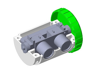
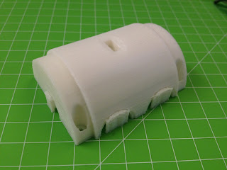
For the body of the robot I wanted to make use of my 3D printer. There are two half shells that hold the servos, the ultrasonic sensor and all remaining electronic components. These halves are connected by four screws. The holes are designed to fit the mounting screws that came with the servos.  Both wheels are screwed into the servo shafts. The heavier parts like the battery need to be in the lower half to help the robot remain balanced.


The stl-files are available on Thingiverse:


Depending on your printer and servos you will have to sand the shells down a bit. The remaining electronical parts are then just hot-glued in.

Programming

This part was pretty simple as well, because I could reuse most of the code from my biped robot (http://coretechrobotics.blogspot.de/2013/12/an-attiny85-ir-biped-robot.html).
The Attiny will listen for infrared signals and moves the servos depending on what it receives.
I also built in an autonomous mode than can be activated by pressing a certain key on the remote. It simply drives forward until the ultrasonic sensor detects an obstacle, then it turns and drives on.
You can download the code from the Thingiverse page or directly from Dropbox:

https://www.dropbox.com/s/g5myobjc0wyziqw/Canbottiny_source.zip?dl=1

Keep in mind that this particular code may not work for you if you don't have the same Sony remote as me. You will have to change the codes at least, maybe it won't work at all.

Conclusion

As this robot was just supposed to be a qick weekend project, I am very happy with the overall outcome. A lot of people on Thingiverse seemed to like it as well and a few even built replicas. The only problem left is the balancing. If you want the robot to stay level while rolling, you will have to put some additional weight in the lower half. 

Monday, July 27, 2015

Creating a Robotics Simulator


Introduction

If you start writing code for a robot it is inevitable to go through a number of iterations until it works as planned. Arduino already makes this easier but especially with complex walking robots it can be a tedious task to reprogram it again and again. This is where a simulator can be very useful.
For my quadruped robot project I programmed a simulator using Processing. I didn't describe it in more detail at that time but I want to make up for that now.

Processing

I mentioned Processing in almost every blog post so far. That's because I think it is a really powerful  yet easy to learn programming language/IDE and it's a shame that it only has such a small community compared to Arduino. But what makes it special?
  • The IDE is only ~200mb and can be run from a USB drive. Compared to Matlab or Visual Studio this is definitely an advantage.
  • The IDE is very similar to Arduino and so is the language, As long as you are not using arrays or hardware libraries you can copy and past blocks of code between Arduino and Processing. 
  • Code can be compiled for Windows, Linux, Mac and even Android with very few alterations. (http://coretechrobotics.blogspot.com/2014/08/a-universal-bluetooth-remote-app.html)
  • The community may be small but you still can find tons of examples and tutorials online. Also there are libraries for anything, just like with Arduino.

Programming the Simulator

1. Basics

First you need to download and unpack Processing:
https://processing.org/download/?processing    (This tutorial is based on Processing 2.2.1)
Be sure that the newest Java version is installed as well.
When this is done start the Processing IDE.

We will start with drawing a simple rectangle.
There are two basic functions that need to be in a sketch. Setup() is called once on startup and draw() runs until you close the sketch window. In the setup function we need to define the size of the sketch in pixels. For this tutorial we will stick with 1200x800. Now we already have a working sketch. Next we insert a rectangle by using rect(). The four parameters for this function are x-position, y-position, x-size and y-size. There are other shapes like ellipses that follow the same scheme. This diagram from the processing website describes the directions in 2D and 3D space:

Additionally you can fill the rectangle with a color by using fill(). Under Tools/Color Selector you can pick a color and paste its value as a parameter. It is important to use fill() before drawing the rectangle. Changes in something like color or stroke only affect the subsequent shapes.
We won't need outlines for this, so we will eliminate them with noStroke().

void setup(){
    size(1200, 800);
}

void draw(){  
   fill(#FF9F03);
   noStroke();
   rect(100, 100, 500, 500);
}


2. Make it 3D

Turning the square into a box requires a few changes. We need to change to a 3D renderer by adding OPENGL to the size function. Box(size) creates an equal sided cube at the origin (top left corner). The function translate(x, y, z) can be used to move it away from the corner. Rotation is done using rotateX(angle), rotateY(angle) and rotateZ(angle). width and height are referencing the values we added to the size function, translate(width/2, height/2) always makes the cube appear at the center.
To enable anti aliasing we need to call the smooth() function. This will not work without adding background(color), that gets called every cycle to overwrite the screen. Lights() turns the lights on and add shades to the cube.

void setup(){
    size(1200, 800, OPENGL);
}

void draw(){  
   background(32);
   smooth();
   lights();
   
   fill(#FF9F03);
   noStroke();
   
   translate(width/2, height/2);
   rotateX(-0.5);
   rotateY(0.5);
   box(300);
}


3. Mouse controls

3D is kind of boring if you can't interact with it. The easiest way to do this is replacing the fixed rotation values with the mouse position to rotate the cube around while the sketch is running. We need to create two variables, rotX and rotY that well be used as view rotation. The function mouseDragged() is used to write the mouse position to these variables while a mouse button is pressed.

float rotX, rotY;

void setup(){
    size(1200, 800, OPENGL);
}

void draw(){  
   background(32);
   smooth();
   lights();
   
   fill(#FF9F03);
   noStroke();
   
   translate(width/2, height/2);
   rotateX(rotX);
   rotateY(-rotY); 
   box(300);
}

void mouseDragged(){
    rotY -= (mouseX - pmouseX) * 0.01;
    rotX -= (mouseY - pmouseY) * 0.01;
}


4. Importing geometry

Unless you are building Wall-E, a cube won't be a good representation of your robot. Luckily Processing is able to import various 3D files including .obj-files.
For the next steps you will have to download the parts I prepared:
https://www.dropbox.com/s/ymn59u6qw7zbjyi/robot%20parts.zip?dl=1
Create a new folder in the direction of your sketch file and name it "data". Unpack the 5 obj-files to that folder.
We can now import these objects to our sketch by creating a PShape for each of them and using loadShape("file") to assign the obj-file. Replace the box with shape(base) and Processing will draw the geometry. Depending on the units we will have to scale(factor) the object to better fit the screen. I also used the translate command to position the part lower on the screen because otherwise the robot would be off center later.

PShape base, shoulder, upArm, loArm, end;
float rotX, rotY;

void setup(){
    size(1200, 800, OPENGL);
    
    base = loadShape("r5.obj");
    shoulder = loadShape("r1.obj");
    upArm = loadShape("r2.obj");
    loArm = loadShape("r3.obj");
    end = loadShape("r4.obj");
}

void draw(){  
   background(32);
   smooth();
   lights();
   
   noStroke();
   
   translate(width/2,height/2);
   scale(-4);
   translate(0,-40,0);
   rotateX(rotX);
   rotateY(-rotY);    
     shape(base);
}

void mouseDragged(){
    rotY -= (mouseX - pmouseX) * 0.01;
    rotX -= (mouseY - pmouseY) * 0.01;
}


5. Rotating/Aligning multiple parts

Now we will assembly the robot by adding the remaining parts. Use the translate/rotate functions to position the parts. Translation and rotation values will always add up. That means that all parts are in a chain where each link is moved relatively to its predecessor.
If you are using your own robot parts you can find the right translation values in the cad file. If the base is 60mm high you have to translate the next part 60 units and so on. Rotation values are in radians and sometimes it will take a few attempts to find the right ones.
By defining three rotation values as variables we will be able to move the joints in the next step.
If you export your obj-files from a CAD software there will be a second mtl-file containing the color settings and Processing will render it that way. If not, disableStyle() can be used to render objects with the standard fill/stroke setting.

PShape base, shoulder, upArm, loArm, end;
float rotX, rotY;
float alpha = -1, beta = -2, gamma;

void setup(){
    size(1200, 800, OPENGL);
    
    base = loadShape("r5.obj");
    shoulder = loadShape("r1.obj");
    upArm = loadShape("r2.obj");
    loArm = loadShape("r3.obj");
    end = loadShape("r4.obj");
    
    shoulder.disableStyle();
    upArm.disableStyle();
    loArm.disableStyle(); 
}

void draw(){  
   background(32);
   smooth();
   lights();
   
   fill(#FFE308); 
   noStroke();
   
   translate(width/2,height/2);
   scale(-4);
   translate(0,-40,0);
   rotateX(rotX);
   rotateY(-rotY);    
     shape(base);
     
   translate(0, 4, 0);
   rotateY(gamma);
     shape(shoulder);
      
   translate(0, 25, 0);
   rotateY(PI);
   rotateX(alpha);
     shape(upArm);
      
   translate(0, 0, 50);
   rotateY(PI);
   rotateX(beta);
     shape(loArm);
      
   translate(0, 0, -50);
   rotateY(PI);
     shape(end);
}

void mouseDragged(){
    rotY -= (mouseX - pmouseX) * 0.01;
    rotX -= (mouseY - pmouseY) * 0.01;
}


6. Kinematics

For this step we will add a second tab to the sketch where the inverse kinematics and movements are calculated. For this tutorial I reused some of the code from my quadruped robot. Basically, the IK() function converts three coordinates to three angles. SetTime() generates a time value from 0 to 4. WritePos() calls both functions and generates a sine function that looks like a horizontal eight, making for smooth movements of the robot. 
The only thing we need to change in the main sketch tab is calling the writePos() function.
If you look at the code in the second tab, it could easily be run on an arduino without alterations. This is what I did with my quadruped simulator. I tested the code and later copied the entire thing to my Arduino sketch.

Main Tab
PShape base, shoulder, upArm, loArm, end;
float rotX, rotY;
float posX=1, posY=50, posZ=50;
float alpha, beta, gamma;

void setup(){
    size(1200, 800, OPENGL);
    
    base = loadShape("r5.obj");
    shoulder = loadShape("r1.obj");
    upArm = loadShape("r2.obj");
    loArm = loadShape("r3.obj");
    end = loadShape("r4.obj");
    
    shoulder.disableStyle();
    upArm.disableStyle();
    loArm.disableStyle(); 
}

void draw(){ 
   writePos();
   background(32);
   smooth();
   lights();
   
   fill(#FFE308); 
   noStroke();
   
   translate(width/2,height/2);
   rotateX(rotX);
   rotateY(-rotY); 
   scale(-4);
   
   translate(0,-40,0);   
     shape(base);
     
   translate(0, 4, 0);
   rotateY(gamma);
     shape(shoulder);
      
   translate(0, 25, 0);
   rotateY(PI);
   rotateX(alpha);
     shape(upArm);
      
   translate(0, 0, 50);
   rotateY(PI);
   rotateX(beta);
     shape(loArm);
      
   translate(0, 0, -50);
   rotateY(PI);
     shape(end);
}

void mouseDragged(){
    rotY -= (mouseX - pmouseX) * 0.01;
    rotX -= (mouseY - pmouseY) * 0.01;
}


Inverse Kinematics Tab
float F = 50;
float T = 70;
float millisOld, gTime, gSpeed = 4;

void IK(){

  float X = posX;
  float Y = posY;
  float Z = posZ;

  float L = sqrt(Y*Y+X*X);
  float dia = sqrt(Z*Z+L*L);

  alpha = PI/2-(atan2(L, Z)+acos((T*T-F*F-dia*dia)/(-2*F*dia)));
  beta = -PI+acos((dia*dia-T*T-F*F)/(-2*F*T));
  gamma = atan2(Y, X);

}

void setTime(){
  gTime += ((float)millis()/1000 - millisOld)*(gSpeed/4);
  if(gTime >= 4)  gTime = 0;  
  millisOld = (float)millis()/1000;
}

void writePos(){
  IK();
  setTime();
  posX = sin(gTime*PI/2)*20;
  posZ = sin(gTime*PI)*10;
}


7. Final touches

With the code above this is already a fully functional robotics simulator. But there are tons of other things to do with processing. For the last step I added an effect that was supposed to look like a spray can. It ended up a little differently but still looks nice. I also added a directional light, which makes the robot appear a little more realistic.
If you want you can export the entire project to a executable program for windows or any other operating system by clicking on "Export Application".

PShape base, shoulder, upArm, loArm, end;
float rotX, rotY;
float posX=1, posY=50, posZ=50;
float alpha, beta, gamma;

float[] Xsphere = new float[99];
float[] Ysphere = new float[99];
float[] Zsphere = new float[99];

void setup(){
    size(1200, 800, OPENGL);
    
    base = loadShape("r5.obj");
    shoulder = loadShape("r1.obj");
    upArm = loadShape("r2.obj");
    loArm = loadShape("r3.obj");
    end = loadShape("r4.obj");
    
    shoulder.disableStyle();
    upArm.disableStyle();
    loArm.disableStyle(); 
}

void draw(){ 
   writePos();
   background(32);
   smooth();
   lights(); 
   directionalLight(51, 102, 126, -1, 0, 0);
    
    for (int i=0; i< Xsphere.length - 1; i++) {
    Xsphere[i] = Xsphere[i + 1];
    Ysphere[i] = Ysphere[i + 1];
    Zsphere[i] = Zsphere[i + 1];
    }
    
    Xsphere[Xsphere.length - 1] = posX;
    Ysphere[Ysphere.length - 1] = posY;
    Zsphere[Zsphere.length - 1] = posZ;
   
   
   noStroke();
   
   translate(width/2,height/2);
   rotateX(rotX);
   rotateY(-rotY);
   scale(-4);
   
   for (int i=0; i < Xsphere.length; i++) {
     pushMatrix();
     translate(-Ysphere[i], -Zsphere[i]-11, -Xsphere[i]);
     fill (#D003FF, 25);
     sphere (float(i) / 20);
     popMatrix();
    }
    
   fill(#FFE308);  
   translate(0,-40,0);   
     shape(base);
     
   translate(0, 4, 0);
   rotateY(gamma);
     shape(shoulder);
      
   translate(0, 25, 0);
   rotateY(PI);
   rotateX(alpha);
     shape(upArm);
      
   translate(0, 0, 50);
   rotateY(PI);
   rotateX(beta);
     shape(loArm);
      
   translate(0, 0, -50);
   rotateY(PI);
     shape(end);
}

void mouseDragged(){
    rotY -= (mouseX - pmouseX) * 0.01;
    rotX -= (mouseY - pmouseY) * 0.01;
}


You can download the finished simulator from here:
https://www.dropbox.com/s/sr4gk1y5mlxrrid/demoRobot.zip?dl=1

Conclusion

As you can see, programming a simulator like that is no rocket science. If you need help making your own check out the Processing reference https://processing.org/reference/ and the forums http://forum.processing.org/two/. I hope this tutorial was helpful to you and it would be awesome to see more robots in Processing in the future.

Friday, April 3, 2015

BQ Prusa i3 Hephestos Review

Introduction

Looking at sites like Hackaday and Instructables, there is an increasing amount of projects that make use of 3D printers. And it is incredible to see how good the print quality has become in the past few years. Because of this I finally decided to get my hands on a 3D printer myself.
When I first found out about the BQ Hephestos I expected a catch somewhere. It offers a large print bed (215x210x180mm) and an LCD screen for just 500€. This may not look especially cheap compared to other sub-500€ printers like the Printrbot simple metal. But those are hard to come by in Europe and including taxes they often cost the same as high end printers.
The Hephestos is an open source 3D printer based on the successful Reprap Prusa i3 that includes several improvements added by BQ, for example a completely redesigned extruder. BQ itself is a Spanish smartphone and tablet producer whose robotics and innovation department, among other things, develops 3D printers.

Hardware

The kit was ordered directly from the manufacturer and I received the shipment short after. BQ really put a lot of effort into the design and packaging of the parts. There is a box corresponding to each step in the manual which makes it easy to keep track of the countless screws and bolts. The manual itself is nicely done as well. There is a picture with detailed descriptions on every page, it kind of feels like building a Lego kit. If the manual is not enough there is also a built video on BQ's YouTube channel in which the printer is assembling itself. It must have taken someone days to animate that.
The parts themselves have a decent quality and are easy to assemble. A few tools are already provided, e.g. different size wrenches and needles to clean the nozzle. The screws are fitted in the plastic parts using a soldering iron so sanding was only needed on some of them. One issue are the linear bearings. They are extremely noisy and have too much friction, I was lucky to have ordered some cheap bearings from eBay a few month ago so I could use those instead.
The extruder comes pre-assembled and is the same one used in the Witbox, BQ's bigger 1600€ printer. It has a powerful cooling fan which has proven to be very effective. The Hephestos can easily print steep angles and bridge larger gaps without ruining the print. I clogged the nozzle once because of too low temperatures but that was simple to remove.
The electronic components seem to be of good quality as well. They consist of an Arduino Mega with a RAMPS 1.4 shield, 5 motors and drivers, endstops, an lcd panel and a power supply.
It took me about three days to assemble the printer and it makes a very stable impression. Normally you would need to shorten the motor cables to get a clean wiring but I was too lazy to do that. I later added a little switch to the z-axis endstop to turn the power on and off without pulling the power cord.

Software

While many 3D printers include their own software or a customized version of Repetier host, the Hephestos only comes with a set of Cura configurations. This would be perfectly sufficient if there would not be apparent errors in the code: A Cura configuration file includes the start- and end gcode. This is the code for priming the extruder and for moving it out of the way after each print. With the file provided by BQ the z axis will move up 200mm after printing. Now the Hephestos cannot even move that far up so it will hit the upper end and possibly destroy itself if you can’t pull the plug fast enough. Secondly the coordinates are not absolute but relative in BQ's code. This means that instead of retracting the filament a bit after the print, it will rewind the entire length of filament you printed. Those errors are simple to fix if you already know about 3D printers but if you have no prior knowledge you will eventually end up destroying the printer.
At least the Marlin drivers provided are working fine. The only complaints I have are the strange LCD menu where you need to tap through 6 submenus to move the axes and the bad temperature control, which is sometimes 5 degree off during prints.

You can download the fixed Cura profile with improved purging here:
https://www.dropbox.com/s/ywu9uwuzllz1jon/CTHephestosCuraProfile.ini?dl=0

Print Quality

There was only little calibration necessary to make the first print and I was really impressed by the quality. At a closer distance you can see that the printed parts are not made by a high end printer but you have to keep in mind that this is practically the cheapest 3D printer you can buy in Europe at the moment. The prints are smooth and have acceptable tolerances which should be more than enough for everyday objects.
I am currently printing on painter’s tape on which the plastic sticks very well. Previously I have been using a glue stick on the glass bed but the undersides of the prints came out very rough that way. Hairspray did not work for me as well, maybe it was just the wrong brand.
The print quality strongly depends on the filament. For the first few weeks I have been using blue PLA from BQ which is sold for 20€ per kilo. This is really cheap and unfortunately you can see that on the prints as well. Later I switched to white formfutura PLA which costs 30€. As you can see in the pictures below the layers look much more accurate and smooth.


Summary

The BQ Prusa i3 Hephestos is a great 3D printer if you are on a low budget and don’t need to print highly detailed objects. With its big print bed and solid construction it is a great printer for hobbyists and tinkerers.
I’m not sure if the printer is suited for total beginners like BQ is advertising it but as it is an open source design you can profit from the reprap community and many questions have already been answered on their forums. You can download every printed and non-printed part from BQ's github page and many people already have made their own additions on thingiverse.


Printed Models:
     Scripted Vase www.thingiverse.com/thing:104694
     Stanford Bunny http://www.thingiverse.com/thing:3731